ARTICLE
Wildlife radiology
Erica A. Miller
Wildlife Futures Program, University of Pennsylvania, Kennett Square, PA
Abstract
Radiographs are a common, non-invasive diagnostic tool useful in many wildlife cases. This article provides a brief overview of radiology as it pertains to wildlife rehabilitation: what are x-rays and how they produce radiographs, factors to consider when purchasing equipment, safety concerns when working around x-rays, indications for taking radiographs, and restraint and positioning of the animal during the process. The reader is encouraged to use the suggested references and work with an experienced veterinarian or veterinary radiologist to practice distinguishing normal radiographs from abnormal.
Bio
Erica Miller worked full time as a wildlife veterinarian for 25 years. She is the Field Operations Manager at the Wildlife Futures Program and an Adjunct Associate Professor of Wildlife Medicine at the University of Pennsylvania School of Veterinary Medicine. She volunteers at Mercer County Wildlife Center and Tri-State Bird Rescue & Research.
Keywords
Radiograph; radiology; diagnostics; wildlife rehabilitation; x-ray; radiography; positioning
Abbreviations
ALARA = As Low As Reasonably Achievable
CR = computed radiography
CdCr = caudocranial
CrCd = Craniocaudal
DR = digital radiography
DV = dorsoventral view
GI = gastrointestinal
kVp = Kilovoltage
VD = ventrodorsal view
Citation: Wildlife Rehabilitation Bulletin 2022, 38(1), 17–27, http://dx.doi.org/10.53607/wrb.v38.242
Copyright: Wildlife Rehabilitation Bulletin 2022. © 2022 E.A. Miller. This is an Open Access article distributed under the terms of the Creative Commons Attribution-NonCommercial 4.0 International License (http://creativecommons.org/licenses/by-nc/4.0/), permitting all non-commercial use, distribution, and reproduction in any medium, provided the original work is properly cited.
Accepted: 15 January 2019; Published: 25 January 2022
Correspondence to: Erica A. Miller, DVM, 1250 Corner Ketch Road, Newark, DE 19711 USA. E-mail: erica@jfrink.com
Introduction
In 1895, Wilhelm Röntgen, head of the physics department at Würzburg University in Germany, was experimenting with a cathode ray tube (later used in televisions) and found that it was causing chemicals in his lab to glow! He had accidentally discovered an unknown type of ray being emitted from the tube, which he called “x-rays” (Thompson 1897). These x-rays were a form of electromagnetic radiation similar to visible light but were shorter in wavelength, which is why they were not visible to Röntgen. He only suspected they existed when the chemicals began to glow, and then he saw that the rays were exposing photographic films kept in the lab. The ability to explain his accidental discoveries and further investigate x-rays led to his receiving the first Nobel Prize awarded in physics in 1901 (Morgan et al. 1987).
Mechanism
Since their discovery by Röntgen, x-rays have become better understood and are currently being used in many diagnostic and therapeutic procedures in human and veterinary medicine. An x-ray machine uses an electric supply to heat a filament (cathode) that, in turn, produces a beam of electrons. The electron beam moves out of the filament toward a tungsten target (anode), interacting with the tungsten atoms and emitting x-rays in the process (Fig. 1). This interaction produces an incredible amount of heat, so a rotating anode was developed to minimize the amount of heat produced at a single spot. The rotor on the machine starts when the exposure button is depressed, getting the wheel up to speed to receive the electron beam. The actual firing of the machine (usually heard as a beep) is the release of the electron beam toward the target. The x-rays emitted by the tungsten atoms are angled to emerge as a beam from the window at the tube head of the machine. The window is the only part of the head that is not made of lead; the x-rays can only emerge from the window as they are absorbed by the lead in all other parts of the head. Lead collimators can be adjusted to change the size of the window, blocking out part of the beam, and absorbing more or less of the x-rays as the beam size is adjusted.

Fig. 1 Schematic of a tube head of an x-ray machine. The electrons (E) move from the cathode (C) toward the anode (A), striking the rotating surface (R). A beam of x-rays (X) is emitted, which passes through the collimator (cm), “focusing” the beam of x-rays as it travels toward the patient and the film cassette. Adapted from Eastman Kodak 1980.
Once the x-rays leave the window, most of them travel in a fairly straight line, and their short wavelength allows them to travel through anything in their pathway that is made of “light” atoms (flesh, towels, etc.). Heavier atoms, such as those occurring in most metals and minerals (including calcium), absorb the x-rays.
In film radiography, the x-rays that pass through materials made of “light” atoms pass through the outer covering of the film cassette, through an intensifying screen, through the film, and are absorbed by lead in the back of the cassette. As the x-rays pass through the film, they cause an exposure of the film. The faster and more numerous the x-rays, the more they expose the film (i.e., the blacker the film appears). Thus, the x-rays that pass through air are slowed down the least, so they produce the most energy and the film appears black. The x-rays that are slowed down some by tissues have less energy, so the film appears to be gray. Most of the x-rays that strike bone are absorbed by the calcium, so they produce an even lighter image on the film (and the less calcium in the bones, the more gray they appear). The x-rays that strike metal are completely absorbed, so the film appears completely white in those areas.
With the advent of computed radiography (CR) and digital radiography (DR), the x-ray beam is converted into a digital image which can then be viewed, enhanced, stored, and shared via any computer. In the case of CR, the x-rays activate a phosphor image plate in a special CR cassette, and a separate reader converts that data to a digital image. DR, on the other hand, uses an active matrix flat panel containing an active matrix of thin film transistors and photodiodes which are activated by the x-rays to create a real-time digital image that is sent directly to the computer.
When and why
Radiographs are a valuable diagnostic tool for finding and characterizing fractures, foreign bodies (ingested or impaled), joint damage or arthritis, change in organ size (normal seasonal changes in gonads or changes due to disease processes), presence of eggs or fetuses, organ displacement, and in some cases, disease processes. Radiographs may also be used to monitor the response to treatment (e.g., change in organ size or appearance or the healing of a fracture). Radiographs are sometimes used to verify wildlife crimes, such as illegal shooting, or exposure to metallic foreign bodies that were ingested by the animal.
Techniques
As the exposure depends on both the number and the speed of the x-rays produced and traveling through the tissue to the film, several things can be done to alter the amount and speed of the x-rays, thus allowing them to penetrate more or less tissue. While the images produced by most digital x-ray systems can be corrected after the exposure is made, using the correct settings before the exposure will increase the quality of the resulting image.
- kVp is the amount of energy used to produce the x-rays. The higher the kVp, the greater the penetrating power of the x-rays produced.
- Time (in fractions of a second) is the duration of the emission of the beam. Shorter time exposures will limit the number of x-rays to reach the film; longer time exposures mean more x-rays. The exposure time for most birds and small mammals is usually 1/120–1/60 second but will vary with the mA and kVp.
- Current (milliamperes or mA) is the number of electrons flowing per second; essentially, the intensity of the x-ray beam. The higher the mA, the more intense the x-ray beam.
- Distance (inches or centimeters) is the distance between the tube head and the film, and can also determine the intensity of the image. The smaller the distance, the more intense the x-ray beam and the resulting image. Distance is most commonly set at 40 inches (101.6 cm) (Morgan et al. 1987).
Equipment
The large variety of x-ray machines, cassettes, films, processors (or plates and panels, in the case of digital x-ray), and other related x-ray equipment available is far beyond the scope of this study. A number of factors are involved in choosing the correct equipment for use with wildlife, including the size and number of animals expected to be radiographed each year, the amount of physical space available in the facility, any applicable governmental regulations regarding x-ray equipment and use, and the finances available for equipment, supplies, and ongoing maintenance.
A few statements, however, can be made regarding radiographic equipment in wildlife rehabilitation. The majority of wildlife patients are rather small (under 15 kg or approx. 35 lb), and therefore, a machine producing a low kVp (40–70 kVp) and a high mA (up to 300 mA) is preferred (Hoefer 1998). However, an amperage as low as 20 mA can produce very good radiographs when used with either high detail films (e.g., blue speed or mammography film) and intensifying screens (e.g., rare earth), or, in the case of DR, an imaging plate or an x-ray image receptor with a high detective quantum efficiency (Naldo 2000). This output range can usually be obtained from small, portable units, which are often easier to house and less expensive than large, stationary units.
Digital radiography uses the same machine for x-ray production but different means to capture the image. In CR, x-rays produce an image on an imaging plate, which is then scanned and digitized with a CR reader before being sent to a computer for viewing. In direct DR, the digital image is captured directly on a flat panel detector and transfered instantly to a computer for viewing.
Care and cleaning
Most x-ray machines should be turned on at least 10 minutes prior to use, so that the filaments can warm up sufficiently.
All surfaces of the machine can be cleaned with either a spray cleaner such as Windex® (S. C. Johnson & Son, Inc., Racine, WI) or a general disinfectant. Other equipment, such as lead shields, aprons, outer surfaces of the film cassettes or imaging plate, and tabletop, can also be wiped clean in a similar manner after each use; screens (insides of cassettes) can be cleaned with commercial screen cleaners using a non-abrasive substance such as cotton balls. DR panels and CR cassettes must be clean and dry at all times. They can be protected with commercial, weight-bearing cases or extra-large (10 gallon) storage bags
X-ray film
If cassettes and x-ray films are being used, the choice of film should be matched with both the machine and the types of screens in the cassettes. Fine or detail intensifying screens can be used with detail film to maximize detail while keeping exposure time to a minimum (Hoefer 1998). The author used single emulsion mammography films and cassettes for producing ultra-fine detail with short exposure times, yielding high-quality images of small animals, such as songbirds or infant mammals. Dental film, which is used without a screen, has also been shown to give good images in very small patients (Hoefer 1998).
An x-ray film should be stored on edge (not flat) in a dark, cool environment with low humidity. Individual sheets should be handled carefully to avoid oils from hands interfering with the chemicals on the film, and to prevent creasing or bending of the film.
Safety
Although there are guidelines for what are considered “safe” amounts of radiation exposure, no one knows for certain just how much exposure is needed to cause tissue damage (either direct cell damage or genetic mutation, that is, cancer). Precautions should always be taken to minimize the amount of potential radiation exposure. Rapidly multiplying tissue is most susceptible to the harmful effects of radiation; therefore, the thyroid gland, reproductive organs, and corneas are the most vulnerable and should be protected first.
Most states have specific requirements for radiation safety training and for licensing or permitting of equipment. Most states also require annual inspections of all x-ray machines. Additional information on safety requirements and licensing of x-ray equipment may be found at <https://www.dm.usda.gov/ohsec/rsd/xpe.htm>.
Minimizing exposure
As there is no specific ‘lower limit’ of known safe x-ray exposure, the general rule for safety guidelines is referred to as ALARA: As Low As Reasonably Achievable, i.e., do everything possible to minimize exposure, while still accomplishing the job of taking radiographs (Widmer et al. 1989). The best ways of minimizing exposure to x-rays are by minimizing the time we are exposed, maximizing the distance between the x-rays and ourselves, and shielding the x-rays.
- Time. Use as short an exposure time as possible and take only as many radiographs as are necessary for the diagnosis. If multiple people at one facility are qualified to take radiographs, make certain that this task is distributed evenly, so that one person is not receiving all of the exposure.
- Distance. Keep hands, arms, and eyes as far from the x-ray beam as possible, and use passive restraint devices such as Plexiglas® boards, Miami Vise® Avian Restraint (Veterinary Specialty Products, Inc., Boca Raton, FL), masking tape, Velcro® (Velcro USA, Inc., Manchester, NH), sandbags, pipe cleaners, or ties whenever possible, and use the collimators to minimize the size of the exposure field (Figs. 2 and 3).
- Shielding. Always wear a lead apron when taking radiographs, and wear lead gloves or shield hands with lead if they are anywhere near the beam (Note: hands should never be in the beam). Lead, thyroid protecting collars should also be worn. If the walls do not contain lead, standing behind a wall does not provide any additional protection; however, a lead-impregnated plastic shield and eyeglasses do provide good protection (Hise & Schuchman 1984).
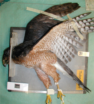
Fig. 2 An anesthetized red-shouldered hawk (Buteo lineatus) positioned for a right lateral, full-body survey view using a Plexiglas® restraining device; wings are taped in place with masking tape.
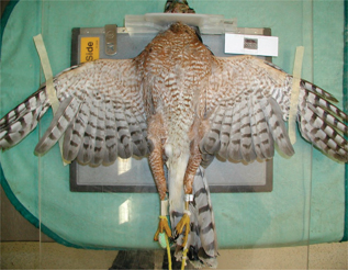
Fig. 3 An anesthetized red-shouldered hawk positioned for a full-body VD survey view using a Plexiglas® restraining device. Pipe cleaners are used to pull the legs straight.
Monitoring exposure
The exposure of the film is measured by how “dark” it develops; human radiation exposure, however, is measured in millirems (mrem) by dosimeter badges worn while taking radiographs. In the United States, the National Council on Radiation Protection has set the maximum permissible full-body exposure dosage at 5000 mrem/quarter and the maximum permissible extremity exposure at 50,000 mrem/year; some states may have lower allowable exposure levels than these (Head 2002). The badges only work if they are always worn while taking radiographs, and only if the users wear their own badges, not someone else’s badge. The badge should be worn close to the neck or thyroid region to measure the exposure to this critical region of the body. The exposure of the badge is measured against a control badge, so the control should never be placed in the room with the x-ray machine. When not in use, all badges should be kept together in a shielded area. Badges are usually sent to the monitoring company monthly or quarterly; the company then reads them and issues a report of each individual’s exposure level. Reports should be used to increase safety measures and reduce exposure as necessary.
Positioning
Poorly positioned films are non-diagnostic. Take time to position the animal properly and be consistent! Two views, taken 90° from each other, are required for nearly all situations; occasionally, a single view may be sufficient to reveal gunshot, foreign objects, or severe fractures.
Restraint
- Manual. (animal is awake or non-sedated) A small towel placed over the eyes will help reduce stress.
- Chemical. Most birds and small mammals can be masked down briefly with isoflurane inhalant anesthesia using a non-rebreathing anesthesia system. Other chemical methods of restraint can also be used with the appropriate oversight of a veterinarian.
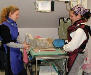
Fig. 4a Positioning a bird for a CdCr view of the left wing.
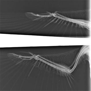
Fig. 4b Radiographs from the right wing of a barred owl (Strix varia) positioned for a CdCr view (above) and a VD view (below). Note that the ulna fracture appears to be aligned in the VD view but not the CdCr view.
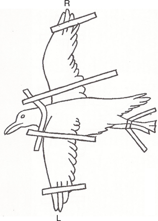
Fig. 5a Diagram depicting the positioning for an oblique scapular view; affected scapula (R) is closest to the cassette and the top wing (L) is pulled down (Papscoe et al. 2001).
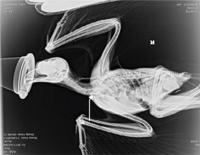
Fig. 5b Oblique scapular view of a great horned owl (Bubo virginianus); affected scapula (R) is closest to the cassette and the other wing (L) is pulled down, making the full R scapula visible (arrow).
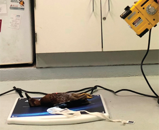
Fig. 6a Positioning the x-ray beam at a 45° angle for the caudoventral-crandiodorsal oblique (H) view; bird is positioned on its back with its feet toward the x-ray beam.
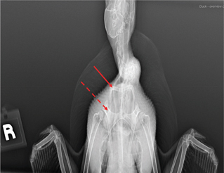
Fig. 6b H view of a teal showing clavicles (solid arrow) and coracoids (dotted arrow).
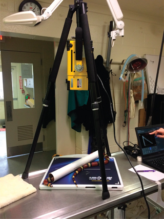
Fig. 7a A cardboard mailing tube is used to position a snake for a full-body DV view.
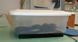
Fig. 7b Black rat snake (Elaphe obsolete) placed in a plastic storage container for a full-body DV view.
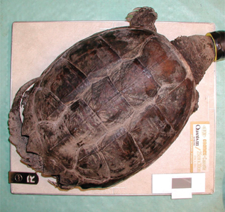
Fig. 8 An anesthetized snapping turtle (Chelydra serpentine) positioned for a full-body DV view.
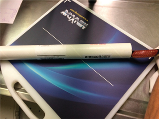
Fig. 9a A snake is positioned for a right lateral view.

Fig. 9b DV view of a snake restrained in a cardboard tube.

Fig. 9c Lateral radiograph image of the snake in Fig. 9a.
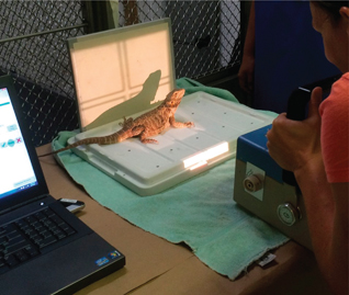
Fig. 10a Using a lateral x-ray beam to take a left lateral view of a lizard.
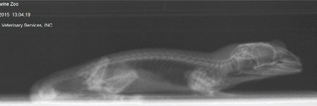
Fig. 10b Left lateral view of a lizard.
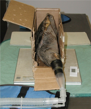
Fig. 11 A cardboard box is used to position a snapping turtle for a R lateral view.
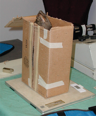
Fig. 12 A cardboard box is used to position a snapping turtle for a CrCd view.
Birds
Most birds can be adequately restrained manually or mechanically, without anesthesia; however, anesthesia may be helpful to minimize stress in some birds, may provide sharper images (reduce motion), and may prevent additional pain or trauma in birds with fractures.
Lateral view—Lay the bird on its side (injured side down, when applicable); wings are extended up over the back, with the “down” wing (closest to the cassette or imaging plate) pulled slightly cranially.
The legs are extended ventrally and caudally to avoid superimposing them on the body, with the “down” leg slightly cranial (Fig. 2). When positioned in this manner, the right and left acetabulae, ribs, coracoids, and kidneys will be superimposed.
This view is good for evaluating the spinal column, long bones of the legs and wings, clavicles, and organ condition.
VD—Position the bird on its back so that the keel is superimposed over the spine; wings are extended perpendicular to the spine; legs are pulled straight out and down on either side of the tail (Fig. 3). When positioned in this manner, the pelvis and pectoral girdle should appear symmetrical, and the right and left femurs and scapulae should be parallel to one another.
This view is good for evaluating long bones of the wings and legs, air sacs, organ condition, clavicles, coracoids, and spinal column.
Caudocranial (CdCr) wing view—Hold the bird, head pointed down with both wings folded into the body, over the edge of the table; gently extend one wing, so that the leading edge (patagial tendon) is in contact with the cassette or panel (Fig. 4a and b).
Oblique Scapular view—Lay the bird on its side (injured side down, when applicable), wings extended up over the back, with the injured wing closest to the cassette or panel as in the lateral view. The legs are extended ventrally and caudally to avoid superimposing the body, with the legs lined up evenly on top of each other. The “top” wing is then pulled down, keeping the bird on its side (not on its sternum). This position allows a clear view of the entire scapula (Papscoe et al. 2001) (Fig. 5a and b).
Caudoventral-craniodorsal oblique view (H) view—Position the bird in dorsal recumbency and allow the wings and legs to remain in a resting, flexed position. The x-ray machine is then rotated so that the beam is centered on the thoracic inlet and angled 45° cranially relative to the plane of the x-ray table (Fig. 6a and b) (Visser et al. 2015). This view provides good evaluation of the coracoids and clavicles not provided in other views.
Separate views (usually VD and lateral) can also be taken of specific body parts, such as head and feet, as needed.
Reptiles
Most reptiles can be adequately restrained manually or mechanically without anesthesia.
DV—Snakes can be radiographed in a plastic container, coiled or stretched straight and taped gently to the cassette with paper tape or masking tape, or placed in a plastic or cardboard tube (plastic tubes used to hold posters work well) (Figs. 7 and 9). Lizards are positioned on their abdomens (DV) or backs (VD) with legs taped out from the body; turtles can be placed with the plastron on the cassette or imaging plate (Fig. 8) or in a plastic box if active.
Lateral view—Manually restrain or tape snakes in a lateral position with or without use of a tube (Fig. 9). Lateral positioning of lizards usually requires anesthesia or at least manual restraint—pull legs away from the body with “down” legs slightly cranial.
Alternatively, if the x-ray generating unit is mobile, lateral views of chelonians, snakes and lizards can be done with a lateral beam (Fig. 10a and b). A turtle can also be positioned on its side inside a box or propped up with towels (Fig. 11) to obtain a lateral view; however, this position displaces organs and can make radiographic interpretation difficult.
Craniocaudal (CrCd) view—This view is good for evaluating the respiratory tract of turtles and is best accomplished with a lateral beam. If the x-ray unit is fixed (and a lateral beam cannot be produced), the turtle can be propped so that the tail end of the turtle is on the cassette (Fig. 12).
Mammals
Many infant mammals and small mammals (mice, voles, moles, rats, etc.) may be manually or mechanically restrained; most juvenile and adult mammals will require anesthesia.
VD or DV—Position the mammal on its back (VD) or abdomen (DV), so that the sternum is superimposed on spine (or vice versa); forelegs are extended up along either side of the head; hind legs are pulled straight back on either side of the tail (Fig. 13a and b).
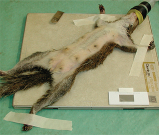
Fig. 13a An anesthetized Eastern grey squirrel (Sciurus carolinensis) positioned for a full-body VD view.
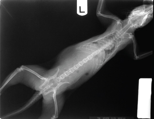
Fig. 13b DV radiograph of the squirrel shown in Fig. 13a.
Lateral view—Lay the animal on its side (injured side down, when applicable); extend the legs parallel to the cassette and perpendicular to the back, with the “down” legs (closest to the cassette) pulled slightly cranially (Fig. 14a and b).
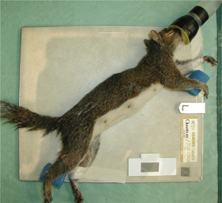
Fig. 14a An anesthetized Eastern grey squirrel positioned for a left lateral view. Note the use of foam blocks to hold the top (right) legs parallel to the table to better assess the joints.
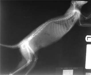
Fig. 14b Left lateral radiograph of the squirrel shown in Fig. 14a.
Fractures
When looking for wing or leg fractures, try to get two views of the affected bone(s), preferably at 90° from each other. For wing fractures from the humerus to the wing tip, this is usually a VD and CdCr. Since the extremities of an animal are thinner and more dense than the main body, the settings on the machine should be changed accordingly.
When looking for vertebral, pelvic (hip), or pectoral (shoulder) fractures, the two views should be VD and lateral. The side with the suspected injury should be closest to the film cassette (down side) for the lateral view. The two views for assessing scapular fractures are VD and oblique scapular, while the two views for assessing coracoid fractures are VD and H.
Soft tissue
When looking for damage or disease in the organs in the thorax (chest) or abdomen (belly), the two views should be VD and lateral. When looking for foreign bodies, such as checking to see the location of a fish hook, two views should be taken at 90° from each other. The exact positions do not matter, as long as two views are taken and the object is visible in both views.
Interpretation (reading/viewing)
Consistency of viewing is important. Always view films so that on the right lateral view, the animal’s head is pointing toward the left; on the ventral-dorsal view, the animal’s right side is on the viewer’s left and vice versa. One of the most important aspects of interpreting radiographs is learning what is normal and what is a radiographic lesion or abnormality. Rubel et al. (1991), Smith and Smith (1992), Krautwald-Junghanns et al. (2010) and Samour and Naldo (2007) are four excellent resources for learning normal radiographic appearances.
Contrast studies
To properly evaluate certain GI conditions (e.g., impactions, torsions, foreign bodies, etc.), radiopaque contrast agents may be administered by gavage under veterinary discretion. In these circumstances, a survey radiograph should be taken to establish a baseline prior to administering the contrast agent. The agent, usually a barium sulfate 30% suspension or iohexol (Omnipaque™, Amersham Health, Inc., Princeton, NJ), is administered orally, and radiographs are taken at various time intervals to evaluate GI function by monitoring the passage of the agent. Doses and transit times for these contrast agents vary greatly depending on the species and health status of the animal, and in reptiles is also temperature dependent (Rubel et al. 1991; Owens & Biery 1999). Dosing an individual animal should be based on the needs of that animal, and it should be conducted in cooperation with an experienced veterinarian or an x-ray technician.
Glossary
- Anode: A positive electrode containing a tungsten target struck by electrons after leaving the cathode
- Cassette: A film holder containing a pair of screens; the film is placed between the screens
- Cathode: A negative electrode containing a tungsten filament that emits electrons when heated Collimator: beam-limiting device containing adjustable lead plates or shutters to change the size of the x-ray beam
- mrem (millirem): A unit of absorbed radiation dose; 1000 mrem = 1 rem
- Rotor: An anode that rotates to avoid overheating in one spot
- Screen: A layer of phosphor crystals bound into a protective coating in a cassette; intensity varies with thickness and crystal size
- Tube head: The main body of the x-ray machine housing the cathode and anode
- Window: The point at which the x-ray beam emerges from the head of the x-ray machine
- X-ray: The ray or beam that exposes a film
Product list
Dosimetry badges for monitoring exposure:
- Landauer, Glenwood, IL 60425, (800) 323–8830, <https://www.landauer.com>.
- Quantum Products, Teaneck, NJ 07666, (800) 359–9686.
Miami vise restraint device:
- Veterinary Specialty Products, Inc., Boca Raton, FL 33 481, (800) 362–8138, <https://www.vetspecialtyproducts.com/>.
X-ray accessories (film, cassettes, protective aprons, gloves, thyroid collars, processors, etc.):
- A Walsh Imaging, Inc. Burnsville, MN 55 337, (888) 235–9729.
- Jorgensen Laboratories, Loveland, CO 80 538, (800) 525–5614, <https://jorvet.com/>.
X-ray machines (analog and digital):
- AFP Imaging Corporation, Elmsford, NY, (800) 592–6666, <http://afpmanufacturing.com/>.
- Innovet, Chicago, IL 60 625, (800) 972–9776, <https://summitindustries.net/innovet-veterinary-xray-equipment/>.
- Sedecal USA, Burnsville, MN 55 337, (800) 920–9525, <https://vetrayusa.com/>.
Disclosure statement
No potential competing interest was reported by the author.
Funding
This work did not require any funding.
References
Eastman Kodak. 1980. The Fundamentals of Radiology. 12th edition. Rochester, NY: Eastman Kodak Company.
Head L.L. 2002. Improving radiation safety in the veterinary hospital. Compendium on Continuing Education for the Practicing Veterinarian 24(11), 858–867.
Hise J.R. & Schuchman S.M. 1984. Lead-impregnated acrylic shielding for a diagnostic x-ray unit. JAVMA 184(1), 95–96.
Hoefer H.L. 1998. Psittacine radiology. In L Keath (eds.): MASAAView, newsletter of the Mid-Atlantic States Association of Avian Veterinarians. Pp. 8–9.
Krautwald-Junghanns, M.E., Pees, M., Reese, S. & Tully, T. 2010. Diagnostic Imaging of Exotic Pets: Birds-Small Mammals-Reptiles. Hanover: Schlütersche.
Morgan J.P., Silverman S. & Zontine W.J. 1987. Techniques of Veterinary Radiography. 4th edition. Ames, IA: Iowa State University Press.
Naldo J. 2000. Radiology. In J. Samour (ed.): Avian medicine. Pp. 50–60. Philadelphia, PA: Mosby.
Owens J.M. & Biery D.N. 1999. Radiographic Interpretation for the Small Animal Clinician. 2nd edition. Philadelphia, PA: Williams & Wilkins.
Papscoe, V.A., Pokras, M.A., Gillespie, E.N., Janeczko, S.D. & Davis, D. 2001. Detection and diagnosis of avian scapular fractures. Wildlife Rehabilitation Bulletin 19(2), 35–41.
Rubel G.A., Isenbugel E. & Wolvenkamp P. 1991. Atlas of Diagnostic Radiology of Exotic Pets. Philadelphia, PA: W.B. Saunders Company.
Samour J.H. & Naldo J.L. 2007. Anatomical and Clinical Radiology of Birds of Prey. Philadelphia, PA: Saunders-Elsevier.
Smith S.A. & Smith B.J. 1992. Atlas of Avian Radiographic Anatomy. Philadelphia, PA: W. B. Saunders Company.
Thompson S.P. 1897. President’s address to British Roentgen society. Archives of Clinical Skiagraphy 2.
USDA Office of Homeland Security & Emergency Coordination Radiation Safety Division (RSD), https://www.dm.usda.gov/ohsec/rsd/xpe.htm
Visser M., Hespel A.M., de Swarte M. & Bellah J.R. 2015. Use of a caudoventral-craniodorsal oblique radiographic view made at 45° to the frontal plane to evaluate the pectoral girdle in raptors. Journal of the American Veterinary Medical Association 247(9), 1037–1041, doi: 10.2460/javma.247.9.1037.
Widmer, W.R., Cantwell, H.D., Shaw, S.M., Vogel, K.M., Hurd, C.D., Han, C.M. & Blevins, W.E. 1989. Radiation biology and radiation safety. Compendium on Continuing Education for the Practicing Veterinarian 11(10), 1237–1247.
Recommended reading
OBI Veterinary Education Inc. 2021. Accessed 12/31/2021 at Additional information on safety requirements and licensing of x-ray equipment may be found at <https://www.dm.usda.gov/ohsec/rsd/xpe.htm> (list of on-line resources applicable to veterinary radiology).
X-rays. National Institute of Biomedical Imaging and Bioengineering. Accessed on the internet 12/31/21 at https://www.nibib.nih.gov/science-education/science-topics/x-rays (easy to understand descriptions and videos about how x-rays work and some of their medical uses.
McMillan M.C. 1994. Imaging techniques. In B. Ritchie, G. Harrison, & L. Harrison (eds.): Avian Medicine: Principles and Applications. Pp. 246–326. Lake Worth, FL: Wingers Publishing, Inc.
Smith B.J. & Smith S.A. 1997. Radiology. In R.B. Altman, S.L. Clubb, G.M. Dorrestein, & K. Quesenberry (eds.): Avian Medicine and Surgery. Pp. 170–199. Philadelphia, PA: W. B. Saunders Company.